How To Install Radiosonde_Auto_RX from a Prebuilt Image

This tutorial has been written to make it easy for someone with little to no knowledge of the Raspberry Pi to set up a radiosonde_auto_rx receive station. The image file used here is also intended to be suitable for advanced users by making the setup process quicker and easier.

The entire process should take less than an hour.

What is Radiosonde_Auto_RX and why do I want it?

Radiosonde_auto_rx, often affectionately known as just Auto_RX is a program written and maintained as part of Project Horus by VK5QI and other members of the AREG radio club (VK5ARG).

You can find the official home of radiosonde_auto_rx on github at https://github.com/projecthorus/radiosonde_auto_rx

In short, Auto_RX is a program which automatically detects the radiosondes attached to nearby weather balloons and decodes the data packets they transmit.   These are the same data packets that your local bureau of meteorology is receiving in order to predict the weather.  Each packet (or frame) usually consists of information such as temperature, pressure and wind speed as well as GPS location and altitude of the balloon.  Auto_RX uses that GPS data to help you plot the path of each radiosonde it hears.

A radiosonde in flight
Radiosonde from a weather balloon laying in a field where it landed
A radiosonde at its landing site – Recovered by VK5DMG
Some radiosondes have a radar reflector attached which can make them easier to spot.

Armed with this GPS data, it can be a great deal of fun to go chasing these radiosondes and recover them from their eventual landing site.  In most places, and at least here in Australia, the Bureau of Meteorology doesn’t even want these radiosondes back, so you can reprogram them to use as transmitters for loads of other ameteur radio projects.

I’m sure you’re thinking “Well that sounds great, but why would I want to track weather balloons?”  Well, there are a few reasons:

  1. Chasing radiosondes is a lot of fun!  Think geocaching, treasure hunting, or foxhunting…  Auto_RX lets us detect where the weather balloon lands and then go out there and attempt to recover it.  Depending how close to the ground we decode the signal, and depending on the terrain of the final location, recovery can be either very simple or rather difficult. Depending on your region, the final landing site could be anything from a suburban area to an outback farm, so there is also a good chance you will get to meet new people when asking for access to farms or backyards etc to recover the sonde.  This can be a lot of fun and these people are often very curious about the balloons.
  2. “STM32 development boards are literally falling from the sky”… If you are a programming and experimenting type of radiohead, then you, like us, will love recovering these radiosondes so that you can reprogram them to do what you like…
  3. Tracking radiosondes is fun and there is a vibrant community!  Tracking anything in the HAM world is fun, but radiosondes are particularly cool.  Not only are there regular and routine launches in your local area, but they are relaying some very interesting telemetry and weather data.  If you are a member of a radio club, there are probably people in your group already tracking weather balloons and maybe even using auto_rx to do it. 

What equipment will I need?

  • A Raspberry Pi (I recommend a 3B, ZeroW or 4B.) –  A case and power supply are a good idea too
  • A blank micro SD Card (16GB or larger)
  • An RTL-SDR (Other SDR types won’t work, it must be an RTL-SDR – I recommend the RTL-SDR Blog V3)
  • An antenna for the SDR  (Reasonable results can be achieved with a simple ¼ wave vertical for the 70cm band)
  • For this tutorial, a Windows computer with an SD Card reader and Win32DiskImager.

No existing knowledge of Raspberry Pi’s is required.

If you need to purchase the Raspberry Pi, case, power supply and SD card, I recommend Core Electronics.

When it comes to the RTL-SDR Blog V3 there are a lot of imitations on the market, some of which don’t perform as well as the genuine item. In the past I have bought SDRs from South Eastern Communications and they have always been the genuine article.

Foreword

I have set this image up to be a very simple way of establishing an auto_rx tracking station.  In doing that I have had to make some basic decisions which may not be ideal for everyone.

Automatic Updates

This image is configured to automatically update when a new version is released.  This automatic updater is my own script which is not supported by the developers of the radiosonde_auto_rx project.  Every day at 16:00 UTC the script will check for a newer version of auto_rx.  This image has also been configured to check for a new version every time the Raspberry Pi is powered on.  There is a possibility that if certain changes are made by the developers to the auto_rx software at some point in the future, my script may fail to work correctly.  In order to use this image, you must accept that risk.  Personally I think it is a very acceptable risk to accept in exchange for a system which keeps itself up to date.  If you want to install this update script on an existing auto_rx system you can find the project here:  https://github.com/Moll1989/auto_rx_auto_update 

SD Card Size

This image requires a minimum SD card size of 16GB.  Originally I was going to make it smaller but;

  1. It’s rare to find a card smaller than 16GB for sale these days
  2. 16GB is actually a good size for auto_rx.  The operating system and software occupies about 3GB, and each log file is typically less than 1MB, so with a 16GB card you won’t need to worry about clearing log files for 5 years if you track up to 7 balloons per day (I track 2-3 per day in my local area).

SSH is enabled by default

I have configured the image to enable SSH by default.  Some may tout this as a security risk, but unless you set up port forwarding on your router to access the pi from outside your network then the security concerns are limited.  I decided to enable SSH so that if any advanced maintenance is required on the pi in future you will not need to plug it in to a keyboard and monitor.

Timezone Settings

The image has been configured to use UTC as the time zone for the pi.  This was done to simplify the automatic updates and reduce the chances of updating during a balloon launch.  Please keep this time zone in mind if reviewing log files etc.

How to do I set it up?

Step 1 – Copy the image to SD card

First you will need to download and unzip the prebuilt image from here: 

https://drive.google.com/file/d/11Dw9kV1J47iC220JEmF2ihkKt6L6uNGy/view?usp=sharing

Now, if you don’t already have it, download and install Win32DiskImager from https://sourceforge.net/projects/win32diskimager/files/latest/download.  Clicking this link should start the download automatically.  Once the download is complete, run the installer and open Win32DiskImager.

Now click the browse button, and select the unzipped image file then click open.

Insert the SD card into the computer, and select the drive letter for the SD card on the right hand side dropdown list.

Now click ‘Write’.  You will be asked for confirmation, as this will wipe the selected device.  If you are 100% sure that the selected drive letter matches the SD card then click ‘yes’.

The image will now be written to the SD card.  There will be a counter indicating time remaining in the lower-right corner of the window.  It is normal for this process to take 5 – 20 minutes depending on your computer and SD card.

NOTE: After the image finishes writing to SD card, Windows will most likely ask you if you want to format the card. If this happens, make sure you click No! This happens because there are actually two partitions created, and Windows doesn’t recognise the Linux partition for the Raspberry Pi operating system, so Windows thinks it is corrupted. It is not corrupted, it is just a non-windows partition.

Step 2 – Configure Network Settings for Raspberry Pi

Once you have written the image to SD card the next step is to configure your network settings.  There are two options for networking, one is to use WiFi, and the other is to use a cabled Ethernet connection.  Whilst I recommend cabled ethernet for simplicity, this is not always practical and both connection methods will perform equally for Auto_RX.  

To configure the network settings, the first thing you will need to do is open the ‘boot’ partition in windows explorer.  In my case this appears as H:  You may need to remove and reinsert the SD card for this to appear after copying the image.

Find the wpa_supplicant.conf file:

If you want to use a cabled ethernet connection, you can simply delete this file.

If you want to use a WiFi connection you will need to open this file in notepad and edit it.  You can do this by right clicking on the file and clicking ‘open with’ then selecting ‘notepad’.

The contents of the file will look like this:

On the second line you need to enter your two letter country code, which for me happens to be AU.

On the 6th and 7th lines you will need to enter your network SSID and WiFi password.  Make sure you click File -> Save when you are finished. Keep in mind that the Raspberry Pi can only connect to a 2.4GHz WiFi Network, so if you have different settings for 2.4GHz and 5GHz make sure you enter your 2.4GHz SSID settings.

Here is an example:

Step 3 – Configure Auto_RX

The next step is to configure the AutoRX software itself.  To do this you will again need to open the boot partition and this time open the station.cfg file in notepad.

This is quite an extensive configuration file with many options.  There are lots of comments in the file to explain the various configuration options. Feel free to have a read of this file and configure it to suit your requirements.  In this article I am just going to guide you through the most essential configuration settings:

SEARCH FREQUENCIES

Firstly, on lines 72 and 73 in the RADIOSONDE SEARCH SETTINGS section, you need to set the scan frequencies.  These are the frequencies which your local weather bureau is transmitting on.  The comments in the code give some good suggestions for frequencies in different regions, but since I live in Australia, the default settings are correct for me.  Radiosondes here transmit on 400.5MHz to 403MHz.

STATION LOCATION

Secondly, we need to scroll down to the STATION LOCATION section.  On lines 101-103 we need to enter our station’s latitude, longitude and altitude. This is important, because our station will appear on the sondehub map and show when we are decoding a particular radiosonde.  If you aren’t comfortable with sharing your exact location, you can pick a rough location within your town or area to enter here.  

Please keep in mind that if your latitude is in the southern hemisphere, you must include a negative (-) symbol before it, and if you are in the western hemisphere, the same applies to your longitude.

SONDEHUB UPLOAD SETTINGS

In the station.cfg file this section is referred to as SONDEHUB / HABITAT (deprecated) UPLOAD SETTINGS.  This is because auto_rx used to upload to Habitat.  Habitat is primarily for ametuer balloon launches rather than meteorological weather sondes, so now all uploads are to Sondehub.org.

The main thing to update here is the Uploader_Callsign on line 131.  Where this says CHANGEME enter your radio callsign.  For example, my station is called VK5CBM_AUTO_RX.

Now save the file.

Step 4 – Plug it in and use Auto_RX

That it!  Now let’s get the system running!

  • Remove the SD card from your computer, and install it into the microSD card slot in the Raspberry Pi.
  • Connect the SDR to one of the USB ports on the Raspberry Pi.
  • Connect the antenna to the SDR and place it somewhere it can see the sky.  Remember line of sight is best, and these balloons go high up in the sky.  As far as 30km high!
  • Plug the power adapter into the Raspberry Pi.

It will take a few minutes for the Raspberry Pi to boot.  The update script will run automatically and fetch the latest version of auto_rx.  Depending on your internet connection, if an update is required it may take up to 20 minutes for the system to finish booting.

A Raspberry Pi set up running auto_rx with an RTL-SDR.

ACCESSING THE WEB INTERFACE

Once the update has completed and auto_rx is running you should be able to access your station. To do this, you must connect from another PC, tablet, phone, etc connected to the same network. You can do this by simply opening your web browser and visiting http://auto-rx:5000 or its IP address followed by port :5000.

If you want to find the IP address a good tool for this is Advanced IP Scanner which can be found at https://www.advanced-ip-scanner.com/  This tool can scan your entire network and list the IP of every connected device.  Depending on how your router handles hostnames, you should see an entry in the list called either ‘auto-rx’ or ‘raspberry-pi’.

When tracking balloons, I highly recommend using https://tracker.sondehub.org as well as your own stations web interface, as this has the benefit of aggregating the data from other receive stations as well.

Summary

Now you are ready to go forth and chase some balloons!

When you do recover one, make sure to head over to sondehub.org and mark it as retrieved, this way others won’t go out looking for the same one you already picked up.

There are some great groups on facebook for radiosonde chasing, such as VK radiosonde chasers which can be found here: https://www.facebook.com/groups/367790020484336

I hope you have found this useful and fun.  Feel free to send any feedback or questions on this tutorial/image to me (VK5CBM) at colin.moll @ gmail.com.

Troubleshooting and Information for Advanced Users

ADVANCED PI USERS – SSH Login

By default this image enables SSH on the Raspberry Pi.  If you need to log in for any reason the username is ‘pi’ and the password is ‘autorx’.

OPTIONAL – Expand the file system on cards larger than 16GB 

If you are using an SD card that is larger than 16GB, you may want to consider logging into the Pi with SSH and using the raspi-config tool to ‘expand the file system’ and make the full card available to the system. There are manyother tutorials on the internet that can explain how to do this.

ADVANCED – PREAMPLIFIERS

One common method of increasing the performance of an Auto_RX station is the addition of a narrowband UHF preamplifier. Several members of our club have had good success with the Minikits amplifier which can be found here: https://www.minikits.com.au/electronic-kits/rf-amplifiers/rf-preamplifiers/70cm-RX-Preamplifier

TROUBLESHOOTING – NOISE SPIKES & FAULTY USB CABLES

Excessive noise spikes can cause problems with decoding packets from radiosondes. Apart from the usual sources of interference a common source of noise can actually be poorly manufactured or faulty USB extension cables. If your station keeps scanning, but doesn’t seem to be decoding you can check for noise by logging into the web interface, open the settings tab and enable “Show Scan Plot”. If you are using a USB extension cable and are seeing noise in the scan plot, then you can confirm whether the cable is responsible by plugging the SDR directly into the Pi.

TROUBLESHOOTING – CALLSIGNS

Make sure that you have no spaces in your callsign. You should only use letters, numbers and underscores.

Links

Win32DiskImager on SourceForge.net: https://sourceforge.net/projects/win32diskimager

The home of the official project: https://github.com/projecthorus/radiosonde_auto_rx

Sondehub, a site for aggregating radiosonde telemetry: https://www.sodehub.org

Habhub, a site for aggregating ametuer balloon telemetry: https://habhub.org

Advanced IP Scanner: https://www.advanced-ip-scanner.com/

AREG write up on their Auto_RX installation: https://www.areg.org.au/archives/209471

Special Thanks

  • VK5HS for introducing me to balloon chasing and using auto_rx
  • VK5QI and the other members of the auto_rx development team for creating and maintaining this software for the community
  • All of the members of the VK5BRL & AREG radio clubs for being so inclusive and supportive

The VK2ZOI high gain dual-band Flowerpot Antenna…

The ubiquitous Flowerpot antenna has been around since about 1993, but the origins go back to the mid 80’s. Have a look at John VK2ZOI’s page for a bit of a history lesson.

The single and dual band versions are cheap to make and perform well, as long as you stick to the dimensions given. They are great for portable and permanent installations, as they are unobtrusive, very light in weight and it’s easy to keep the weather out of them.

They are an excellent club project, and an ideal 1st antenna for a new Foundation licence holder or indeed any licence level. Especially if you’re on a budget!

I got inspired to revisit this antenna when I was rummaging in my shed, and found thiswp-1594454181437.jpg old 2 Metre band Flowerpot that I picked up from the Adelaide Hills  Hamfest, quite a few years ago now. These were offered by (I think) one of the local clubs and were very reasonably priced, so I bought one to try,  with the intention of using it as a packet/aprs antenna. I never did use it, but it was probably best I didn’t,  because when I put it on the nanoVNA it showed it was resonant at about 130 Mhz. This was quite puzzling, but then the penny dropped. The Antenna was made from 32mm PVC,  instead of the specified 25mm. This has the effect of lowering the self resonant frequency of the coil to around 100Mhz. I decided to dissect the antenna in the name of science to check the lengths that the radiators were cut to, and sure enough, they were trimmed for a 2 M half wave flower pot.

As I wanted to make a new base antenna for my home QTH , specifically one that did both 2 Metres and 70 cm, I decided to have a look at the “Experimental Dual Band High Gain Flower Pot Antenna” that John describes on his page here. I built it as shown, but I found that I could only get 6 turns on the 25mm PVC with the published length of the half wave phasing section given. I found it was actually resonant at around 137 Mhz, so I lengthened the 1/2 wave phasing section to give me 7 turns on antenna number 2, and this actually bought the resonance up to 144.2 Mhz. This was looking more like it,  so I trimmed the top radiator length by about 25mm, and this raised the resonant frequency to about 145.5 Mhz. I then added the 2 conductive sleeves as described, using aluminium foil,  to make the antenna resonant on 70 cm. This proved to be very successful. The nanoVNA showed about 1.2:1 on 145.5 and 1.1:1 on 439Mhz. The nanoVNA proved to be an absolute godsend when testing and pruning any antenna, and if you haven’t got one yet, then “Do yourself a Favor” as Molly Meldrum says! Even if you don’t understand the nanoVNA, or the Smith Chart – I didn’t to begin with, the learning curve isn’t steep and you’ll gain a much better understanding of what your antenna is doing and the relationship between SWR and resonance. For the price you just can’t go wrong.

Building it…

***The original Flower pot antenna called for grey 25mm Conduit. I couldn’t find this stuff so I used 20mm PVC water pipe. The outside diameter is 27mm. This seems to be a good substitute, and doesn’t break the design***

The PVC pipe I’m using comes from Bunnings…this should be universally available throughout their stores Australia wide. It is a plumbing pipe, white in colour, and is their 20mm pipe. The outside diameter is 27mm. They sell it in lengths of 3 metres  – you’ll  need one length per dual band antenna. You’ll also need a suitable 20mm endcap for the top of the antenna, and, optionally, one for the bottom, depending on how you mount the antenna, the connector and deploy it.

The Coaxial cable – I used was marked “GME Commerical Grade RG58 Coax” But really, any quality RG58 cable should do.You might like to use marine grade cable, as this is white, and is less susceptible to the ravages of UV from ‘ol Sol if your antenna will be outside in the blazing sun all day, everyday. Make sure the coax is 100% braided, of high quality and has no foil. You’ll also need some kind of a suitable RF connector for the antenna . I highly recommend an N connector, especially for something that will have RF at 400+ Mhz

Aluminium Foil – About 500mm. It’s in your kitchen cupboard.

ToolsA sharp knife, Heatshrink tubing , A Tape Measure, an Electric drill with a 6mm bit and a decent marker.

wp-1594465927338.jpg

Handy Tip 1: Drilling the holes for the coils The 6mm holes in the PVC are made with the drill and elongated at an angle so as to accommodate the cable to smoothly transition leaving the hole and lay flat on the pipe, as shown here at right.

wp-1594461117741.jpg

Handy Tip 2: Winding and counting coil turns – here is how I wind and count the turns on the coils.    S = Start In this example there are 7 turns.

Use the diagram from Johns’ webpage to cut your coax and prep it. The same goes for your PVC pipe. The sleeves are simply aluminium foil from the kitchen…here are some pictures to help you visualise what needs to be done…

Begin by feeding the coax up from the bottom of the PVC to the first hole and then wrapping the 9 turn coil, feeding the remaining coax up to the 3rd hole , winding the 7 turn coil and back in hole number 4 and up to the top. Secure the wire with some line and the end cap as shown,

Finish up by fitting your connector of choice to the coax, and wrapping the coax coils with tape or heatshrink to secure them. Ill leave how you wish to mount the antenna up to you. I just taped mine to the top of an 8 metre length of pipe with some strong waterproof tape and tucked the coax connector back up the PVC pipe to keep it out of the weather…

I checked the antenna back at the shack end of the coax and here’s what the nanoVNA has to say…

Here is 2 metres, the VSWR is 1.2:1 Resistance is 48 Ohms at 146Mhz, reasonably flat across the band…

And at 438Mhz, we have a VSWR of 1.36:1, 50.2 Ohms. Pretty good!

This mean our transmitter is happy to deliver full power into the antenna . How well does it work? For such a simple antenna, the performance is excellent! I’ve had my dualband flowerpot antenna up for a few weeks now, and it’s a solid performer on both bands. Simplex and repeater contacts are no problem, and I’ve been able to regularly get into the Ouyen, Victoria 2M repeater @ 179km away on many occasions, and other, more distant repeaters, especially in the mornings when there is a bit of lift. I’m looking forward to the summer E’s and troppo season.

The antenna has worked well for listening to telemetry from the project Horus balloon launches on its 70cm SSB downlink with my Icom IC910H.

The ISS has recently enabled a dualband repeater onboard with an uplink on 145.990 with a 67Hz tone and a downlink on 437.800. The flowerpot works well here, Even though it’s chaotic to try and get in, I have been able to access the repeater on several occasions, even with elevation angles of only 7 degrees above the horizon.

In short, the dualband flowerpot is great project for your shack, whether you’re a seasoned Ham of just starting out in the hobby. I was motivated to build it because of its low cost and simple construction. This antenna would make an excellent club project. Build one and let me know how you go!

My antenna has now been up for over 6 weeks and its performance continues to impress me.

Andy – VK5LA

A Tuned Counterpoise Vertical for 30 and 20M –

Hi all,

I’m presenting here a compact, completely self contained vertical antenna that I have conceived,  designed and built recently. This antenna is primarily for portable operation on the 30 and 20 metre bands (although it could be easily adapted for other bands). Being a portable antenna, it had to tick a few boxes, as I intend using it on some planned VKFF park activations that will be taking me near salt water…

  1. Be light weight – Fiberglass, aluminium, nylon and stainless construction
  2. Be compact – The entire antenna packs down into a package no longer than 1.5 metres
  3. Be quick to erect – The antenna mounts on one of my ALDI Bike repair stand tripods that I use for portable operations and deploys in minutes.
  4. Plug and play – Low maintenance, simple 50 Ohm Coax feed, no traps, easy to adjust
  5. Be a good performer – Initial tests indicate it is an effective low angle radiator.
  6. Have a very low environmental impact – Some park environments are fragile, so a stand alone antenna that uses no vegetation/natural features as supports protects that environment

Tuned5LA

Fig. 1

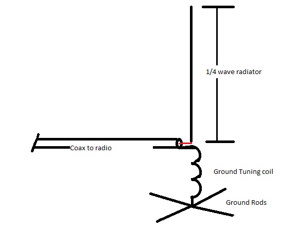
The inspiration for this antenna came after I came across this video from Peter, VK3YE back in 2015 on his most excellent YouTube channel. The construction details on his antenna were unfortunately rather brief, but used telescopic rabbit ear TV sections as his counterpoise, and a section of coil stock which he taps to bring the counterpoise to resonance against a quarter wave radiator. It’s wonderfully simple. Peter drew a diagram in the sand, but i’ll put one here…

Figure 1 shows the antenna. It consists of a 1/4 wave vertical radiator, with an Elevated, short counterpoise, that is tuned to resonance (think of it as the other half of a dipole with the 1/4 wave radiator) by adjusting the inductance of the ground tuning coil.

I just like to mention that I haven’t invented anything, but other than Peter’s video, I haven’t been able to find any concrete reference or practical examples to this kind of antenna on the internet. Peter mentions a page in Les Moxon’s “HF Antennas for all Locations” describing a short tuned counterpoise, but the second hand copy I hunted down (ISBN 0 900612 57 6) doesn’t have the same information. The diagram shown on page 186 in Peter’s version of the book in the video appears on page 157 in my copy. There is only a vague mention of the same concepts, nor is there any solid measurements or construction tips.

30m-tuned_counterpoise_quarterwave

Fig.2

I have become reasonably adept at modelling and tweaking simple antennas in MMANA-GAL  Antenna modelling software. This is an excellent, free program that lets you visualise and design an antenna, and play with it to tweak its performance. I’m no expert, but after a short learning curve I’m able to do pretty much what I need to do reasonably quickly. So I drew the antenna thus… In figure 2, you can see the feed point – the red dot, the 1/4 wave radiator above it, and the  4 short counterpoise wires below. The ground tuning inductor isn’t shown, but is actually described in software. The wire I used as a radiator is just heavy duty grey plastic insulated wire. It has a velocity factor of about .93 so my 10.135 Mhz 1/4 wave is 6.875 metres long. The counterpoise “wires” –  actually 6mm aluminium tubing, are all 1.5 metres long. The lowest point of the antenna is at 1.00 metres from the ground, as this is the height bottom of the antenna stops when slid on to my portable mast mount. 

Ok, so what about the short counterpoise? How do we tune the antenna to resonance? We know the radiating element is at a 1/4 wave for our band of interest – in this case 6.875 metres long. Let’s add a short wire between the feed point and our 4 counterpoise wires to add a coil to…

W2View

The red wire shown in the model is only 100mm long, but is used to define where we will put our coil to bring the 4 short radials to resonance. This is defined as Wire 2.

Now we have the antenna defined in the program, We need to tell it that we are feeding the Antenna at the bottom of Wire 1. This is in the table Sources 1 w1b. The inductor is defined in the Loads 1 table The coil is defined here as w2c – i.e the coil is in the centre of Wire 2 and has a value of 5 uH. ( This was initially 20uH…it was twaked to 5uH to get the SWR down)

Loads

Ok now we can run the software to see what the antenna model will look like…

Calculate

So here we have the result. Here we can see that the antenna has a feedpoint impedance of close to 40 ohms resistive, 8 ohms reactive with a SWR of 1.33. (This result is after I tweaked the value of the inductor from about 20 uH to 5 uH) The base of the antenna (tuned ground radials) is at 1.00 above real ground.

Lets look at how the antenna is radiating RF according to the software, here are some plots…

Plots

This shows the gain of the antenna is about 1.00 dBi, and the maximum radiation is at around 26 degrees towards the horizon.

Now we have a model that says what I have envisaged, should, in theory, work!

Let’s build it!

Pictures tell 1000 words so here is some shots of the various parts…

The Main radiator is a 9 Metre Squid pole, this slips over a 42mm PVC extension that slides into the top of the ALDI bike repair stand I’m using as a tripod. The top and bottom coil supports are cut and drilled from Nylon cutting board. The 4 radials below the coil attach to the triangular aluminium plate on the bottom coil support. The bottom of the coil is connected here, and the top of the coil is connected right at the earth connection of the SO239 socket on the top coil support. The Coil is soft aluminium craft wire, readily available from ebay. It’s easily formed into a coil and is slightly “springy”. There is a nylon clamp on the top coil support that allows the top support to move up or down, thus stretching or compressing the coil, to tune the antenna to resonance. The clamp secures it when the adjustment is completed. The 1/4 wave wire attaches to the centre conductor of the SO239 socket, and is loosely wound up the squid pole mast and secured. There is a common mode choke just below the feed point, it’s 17 turns of the coax through a single FT240-52 toroid. (shown here as RG174, since changed to RG58)

So what does our trusty nanoVNA tell us? After adjusting the length of the coil this is what the 30M band looks like…The antenna seems to be doing exactly what it should. Feed point resistance is 47.7 ohms, there is 1.36 nanofarads of capacitive reactance and the SWR is 1:1.26 .have to be happy with that…

20200725_124707.jpg

I also experimented with a 20 metre band radiator, and added a shorting clip to shunt out some inductance to bring it resonance on 14.075…Here our SWR is 1:1.19…so its working here as well…

So how does it work on the air? It’s early days, and I had it set up very close to my house and fence, but the path to my east was clear and it certainly seems to get out. Some good DX to El Salvador and Guatemala on 30 metres FT8 was worked in the first few hours on the air…I easily worked the USA as well on both 20 and 30 metres. (all East of me)

I’ll set this Vertical up in the clear on my block away from buildings in the next couple of days and see how well (or not) it works compared to my reference antenna. I’m hoping the low take off angle will allow me to work the more distant stations my reference antenna seems to struggle with.  I’ll update here when I’ve had more time to judge it’s performance.

I hope the information presented here is of interest to some. I really enjoy modeling and building antennas, but I’m pretty green! I’ll readily admit to not understanding many aspects of RF and I have no idea how efficient this antenna is, my ground losses, etc etc. I guess it’s all about learning and experimenting. I welcome any comments or criticism, please feel free to contact me if you would like any more details on what I’ve described here…

73

Andy, VK5LA

andyvk5la@gmail.com

***UPDATE***

Very happy with the antenna, I worked 100 countries in 7 weeks, pretty good going at solar minimum!

Some ideas for RX noise reduction and a Mains Filter for your Radio Shack…

Got Noise? -Then this might get you back on HF if you’ve switched off because the “S” meter is S9 or S9+ when you turn on your rig, especially on the lower 160-80-40-30 Meter Bands…

If you live in suburbia, or even semi-suburbia, you might have, or are currently dealing with, high levels of noise in your Receiver when operating your radio. This is usually the worst when you’re trying to work that rare DX, a weak digital signal or even just your club HF net or Society news broadcast. Noise can be wearing. I have heard of many an Amateur that has switched off due to excessive noise and placed their hobby in the “too hard basket”. I even personally know of two radio friends who sold up and “moved to the country” in search of that holy grail of noise levels…S0.

I don’t claim I’m going to fix your noise issue but hopefully I can offer some guidance and experience in dealing with radio noise in the HF spectrum in your environment.

Firstly, If you can, set up your radio to run of of a battery and plug in your main antenna. Cut the power to your WHOLE HOUSE, (yes go out to your meter box and throw the main switch!), so that nothing is energised on your property. (Also cut your Solar if you have it and are able) Now see what your noise level changes to. Chances are, the noise level will drop, sometimes significantly. This is actually a good thing, because it means that it is highly likely that the noise source is at your place, and you can do something about it. More later.

If your noise doesn’t change significantly, then the likely scenario is that that your antenna is picking up a noise source from a neighbor, or a utility such as a nearby power line or other service.

***My first piece of advice is to make sure that your antenna feed line has a common mode choke.***

This will need to go at the feed point if it is a coax fed dipole or variant, or right at at the radio if it your antenna is an End Fed Half Wave or similar. If you are unsure what a common mode choke is, then grab a coffee, and  have a look at this from Steve, G3TXQ (SK).

Now have a read of this from Jeff, K6JCA. Both links are extensive and extremely informative.

If you’re still not convinced that you need some kind of common mode choke on the feedline of your antenna, please have a look at this video.  You can clearly see the effect on both Receive and Transmit.

Now back to our main objective, let’s look at another known source of noise, the very common Switch Mode Power Supply. These. things. SUCK!!! They are known generators of RF noise and interference. Generally, their cost is inversely proportional to the amount of RF they generate! The cheaper units leave off a few cents worth of EMI suppressing components to make them as nasty as can be. Most modern households these days have many gadgets and low cost Asian electronics, and they often come with one of these Switchmode power supplies. Phone and Tablet chargers, computer and laptop power supplies, garden and Christmas lighting, toys, decorations and fixtures containing electronics, LED light fittings and bulbs…Just about everything these days has an SMPS. Some are clean, but many can be excellent generators of broadband RF hash. Indeed, some can completely wipe out radio reception up into the UHF range, (like the charger our boys portable DVD player!!!)  The best way to find them is by a process of elimination, simply by going around the house and turning stuff off at the wall. This will soon expose the culprit , but don’t forget you need to cut the power to the particular device completely, not with just switching of with a remote or the front panel power switch, as this usually just turns off the displays, (think home electronics, Audio Visual gear etc. etc.) and the unit is still effectively powered up, and still drawing current from the power supply.

I had a particular problem with the power supply for my shack laptop, which is a Dell Lattitude E6410. Even though Dell is a reputable brand, used by business and governments around the Globe, the power supply generated a bad hash causing up to an S7-8 noise level, from 80-20 metres.

wp-1591267938406.jpg

Simply wrapping the power connector lead through a FT240-43 Toroid core as pictured above, went a long way to eliminate this noise. The difference was remarkable. A point to note was that the power supply itself had just about every compliance tick and UL listing .

wp-1591269468755.jpg


They mean nothing!


***My second piece of advice – hunt down, find and eliminate any cheap Switchmode Power supplies***

Replace them if you can, or alternatively get some ferrite rings and wrap the output leads through the cores as many times as you can.

Other sources of noise can be from the cables coming from your shack computer to peripherals such as printers, keyboards and mice, displays and USB leads and hubs etc.etc. Give these the toroid treatment as well, everything helps. (As an example, here is the USB lead from my laptop to the USB mixing desk I use to route microphone and other audio to my main HF radio directly into the balanced modulator), and to the little Raspberri Pi I use for digi modes. These all help in the scheme of things to drop your RX noise closer to S0. If possible switch to a bluetooth mouse and keyboard if you’re running a PC . This eliminates 2 leads from radiating computer hash in your shack.


Sometimes, noise can come from the 230V mains supply to your shack from many different sources. Perhaps from an appliance located at your or a neighbours house, such as a dishwasher, washing machine, deep freeze, hot water heater, solar hot water booster, microwave etc.etc if they are on the same supply phase. The noise this equipment can generate could radiate to your station via your power supply.

This is where this mains filter comes into play. Just like a common mode choke on our feed line (you have installed one, haven’t you?) the best way to eliminate or greatly reduce supply noise is to have a mains filter that incorporates a 2 stage EMI Filter with some hefty, multi frequency common mode choking of the 230V supply, before it powers the equipment of your shack.

After doing a bit of reading and on the advice of others, I was directed to this most excellent presentation describing a holistic approach to finding and eliminating such noise and the construction of such a filter by Ian White, GM3SEK, and the update here.

Here I’m describing my version of the filter that I built. Anyone should be able to reproduce this filter, using parts that were easily obtainable here in Australia. My parts came from Jaycar, RS components, Bunnings and Cheap as Chips.

***Disclaimer – this project describes working with Mains Voltage!!! ***

***If you are not experienced with working with the 230V mains wiring, find someone with expertise to assist and check your work!***

Parts List:

  • 1 x Sealed Polycarbonate Enclosure 171 x 121 x 80 Jaycar Cat No. HB6224
  • 1 x EMI Filter  – I had mine laying around, see Note 1 – RS Components
  • 1 x Fair -Rite Large Ferrite core (clamp type) RS Components Stock No. 466-9164
  • 4 Small Ferrite cores, Jaycar L15 Cat No. LO1238
  • 1 x 10 amp 12 way Terminal strip (chocolate block) Jaycar Cat No. HM3196
  • 1 x length 10 amp extension lead – Cheap as Chips
  • 1 x 6 outlet power board overload protected – Cheap as Chips
  • 2 x 16mm Cable Glands – Bunnings

Note 1: Delta Electronics 10 DRC5W 250Volt 10A 2 Stage EMI Filter or equivalent. I used one I had kept from an old Photocopier, hence the surface rust ! Just about any EMI filter with a 10 amp rating should do, RS Components lists many single and double stage filters that would be suitable.

A picture tells a thousand words, so here is how my filter came together…

This slideshow requires JavaScript.

wp-1591764985009.jpg

The completed unit with the lid off…


The end result is shown here. The filter simply installs between your wall socket and your equipment. The Cable glands grip the cable to prevent it from being pulled out. Cord grip grommets like Jaycar CAT No. HP0718 would probably be better, but I had the glands, so I used them.

So how does the filter perform? I have been using the filter for a little over a month. My location is quite good for HF and I am blessed with a quite low noise level on most bands, it was reasonably high on both 80 and 30M. I am unsure of the sources (it’s not my place) and my nearest neighbor is 250 metres away. The filter has dropped my 80M noise from S8-9 back to S3-4. this is a significant improvement on that band and I have been able to make contacts I probably would have struggled with previously. My noise on 30M did seem to come and go, noticeably with the operation of our dishwasher and washing machine. There can also be a bit of a noise hash on this band that was sometimes up to S7. I’m pleased to report that the hash has been significantly reduced and my 30M noise level sits at around S1, and I can no longer tell when the dishwasher is on! I like to take a holistic approach to noise and this filter has made a difference.

This is a simple project that might significantly reduce your noise level in the shack – build one and let me know if it works for you!

73 – Andy, VK5LA


An update to the 40M Half Square antenna

I thought I’d give an update on this antenna since I’ve had several emails and messages enquiring about it. The antenna has been up for 3 weeks, and I’ve had over 500 QSO’s and worked some great DX, mainly using FT8 mode on 17, 20, 30 and 40M.

I ended up with a broken support after some strong winds so I had to buy a new squidpole for the fed end support. This new 9M pole ended up being about 1 metre shorter than the existing pole when added to the extensions. This has bought the feed point about a metre closer to the ground, and I’ve added a 200cm piece of fibreglass rod to the tuning cap shaft, to make it easier to adjust. I didn’t bother with adjusting the other vertical support leg lower to match, the antenna still works!

20200523_122623

The angle of radiation is also low on 20 Metres and I’m using a 49:1 broadband matching transformer to put power into the antenna and touching up the match via my Radio’s internal antenna Tuner. It’s a reasonable performer on 20, but not as good as it is on 40

Another surprise is the 30M band. Although the modeling suggests the radiating pattern is quite potato shaped, I’ve been able to work pretty much everything I hear when the band is open. I do better into Europe on this band than 40 and 20 Metres

Best DX on 40M looking West (Africa) to date would definitely be Charles, 5H3DX in Tanzania…Al time new country!

20200524_055909

and looking East to the Central America and the Carribean, Dev, 9Y4DG in Trinidad on 30M…(Then Frank, HB9EUW in Switzerland called me!)

a

I have been delighted so far with the performance of the antenna, especially since we are at the bottom of the cycle with no sunspots. I am at 199 DXCC countries worked. Who knows what will happen when ‘ol Sol wakes up!

I have also experimented with a 20M version of this antenna for portable operation. It fits in a plastic sandwich bag, takes minutes to set up, as it is only 2×5 metre lengths and 1×10 Metre length of wire that’s suspended between 2 squidpoles on stands. For the 20, however, I fed this at the 50 Ohm point with some coax at the top of a vertical section. The bottom of the vertical legs were about 1.5M  above ground, to get them away from the stands. This was very promising, as after adjusting the antenna to be resonant at around 14.1 Mhz, I was easily hearing stations from South Africa on the litte FT817. I didn’t bother to reply to them with my 5 watts, but they were good copy. I did have a good contact with Gerard, VK2IO, on 40 Metres, just before I packed up the antenna after my experiments. Gerard was operating from the Yellowmundie Regional Park, VKFF-0558. He gave me a 57, not bad for 5 watts.

The next outing for the antenna will be to use it on an activation in a VKFF park. On 40 and 30 Metres as an end fed, this antenna is looking promising as a decent NVIS radiator, ideal for this king of operating. Stay Tuned!

A Half Square Antenna for the 40 metre band…

Now that there are social distancing rules that have us mostly at home for the near future, I realised that this is an excellent time to do some upgrades to the VK5LA antenna farm.  I have wanted a low angle, dedicated and resonant radiator for 40M for some time, and recent reading had me thinking about trying a Half Square antenna for that band. The full size dimension would fit easily across my my back yard, and I had available the supports required to get it to the correct height.

An added bonus is that I would be utilising Mmana Gal antenna modeling software and my new nanoVNA to observe and adjust the antenna once erected.

Like many other VK hams, I really enjoy watching VK3YE’s You Tube videos, particularly when he heads to the beach and operates portable…it was this video that started me on the journey for this antenna…if Peter’s antenna worked ok on 20M why not try one one of these on 40M at my place?

For those unfamiliar with a Half Square, the easiest way to describe it, is to think of a single staple, like you would find holding a couple of sheets of paper together.

That hasn’t been used yet!

Now orientate it so the pointy points, point at the ground!

halfsquare1

So as you can see in the above screen shot from the Mmana Gal software, here is a diagram of the  antenna. It is simply 2 1/4 wave verticals on 40M joined by a 1/2 wavelength wire at the top. This diagram show it being fed at the top corner (the small red circle) this is a 50 ohm direct feed point, great electrically, but it’s not very convenient to feed it here as *ideally* you have to get heavy coax to this point and lead it away at 90 degrees for a 1/4 wavelength…not very practical…Other more obscure feed methods are feasible, and you can find them on the internet or in good antenna books if you look hard enough. Perhaps the best way to feed it is at the bottom of one of the vertical wires, far more practical, but tricky electrically!  Nothings easy is it? Using the software, we can see in theory how the antenna will perform when fed with RF at our chosen frequency, at the place we want to feed it…

So let’s run model of the antenna in the software. I’ve told Mmana Gal to feed it in a top corner…

HalfSquare

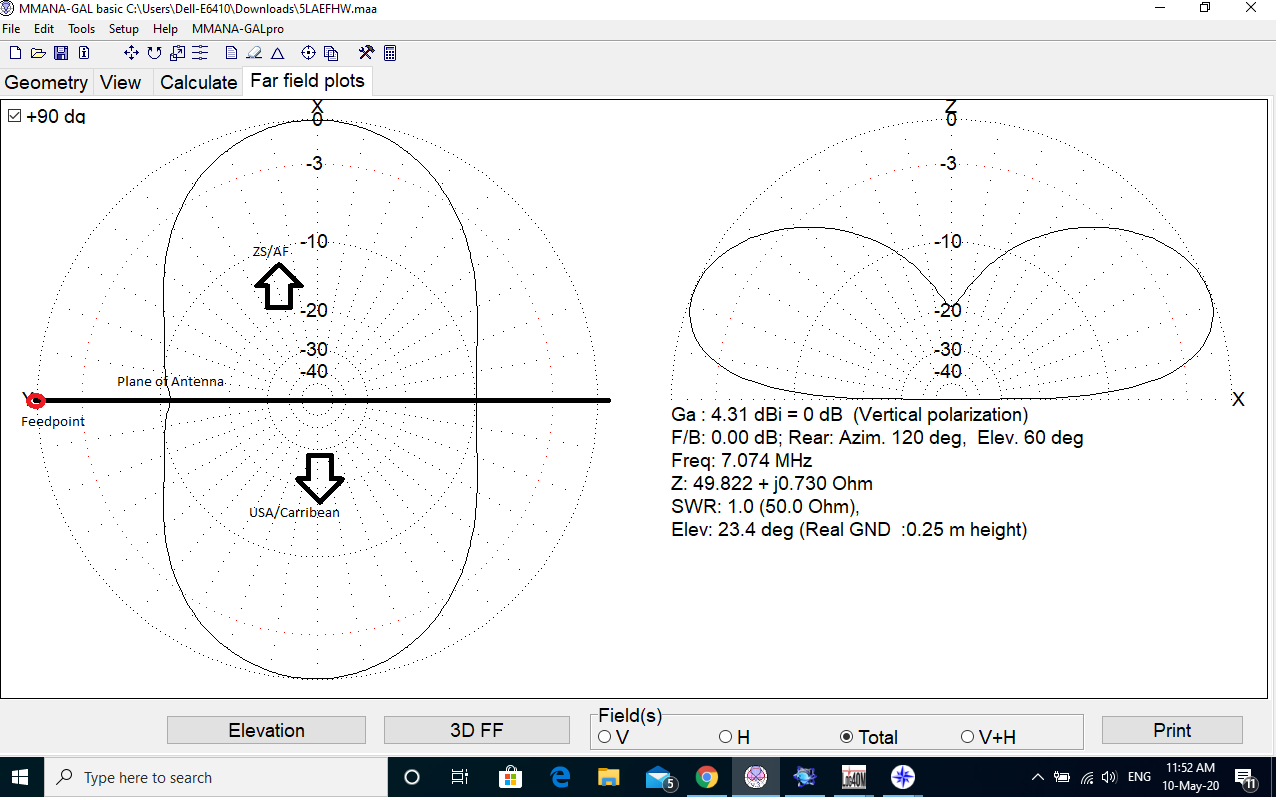
This image above shows the antenna radiation pattern. The diagram on the left shows the antenna, looking down directly on top of it. You can see that the long halfwave section going from left to right, the feedpoint (red dot) is shown for reference. The diagram on the right shows the results of the modeling and the elevation pattern. We can see here, that at our design frequency of 7.074 Mhz (for FT8), the Gain is 4.31dB over an isotropic radiator, there is a 0dB front to back ratio as it’s radiating equally well in 2 directions, the  impedance at the feedpoint is very close to 50 ohms and that the reactance is very nearly 0 Ohms. I made the lowest point of each the 2 vertical radiators 250 mm from the ground, as I wanted there to be sufficient room without having the feed point in the dirt.

Let look and see what happens if we feed the antenna at the bottom of one of the vertical radiators…this is far more convenient…

Halfsquare2

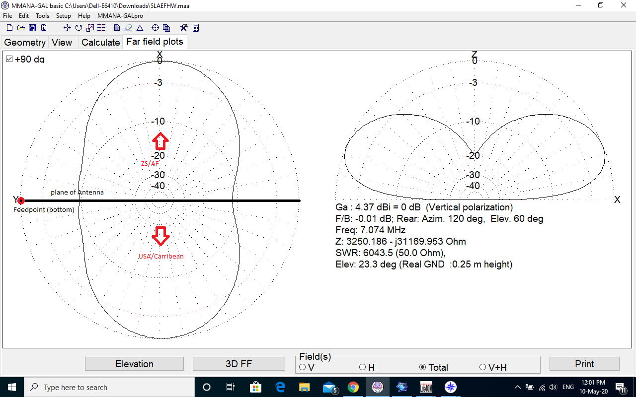
We can see here that comparing the 2 diagrams, the only real change at our 7.074 Mhz design frequency is the resistance at the feedpoint is now at 3250 Ohms with LOTS of reactance. Other important parameters like elevation angle, gain and vertical radiation remains virtually the same.

So there we have it, here are the plots of the radiation patterns, first, horizontal polarisation and then Vertical polarisation…this indicates that at least some of our vertically polarised radiated power should head towards the horizon at around 23.3 degrees. There seems to be very little Horizontally polarised radiation, and what little there is, is going straight up to warm clouds. Vertically polarised radiation, at a low angle towards the horizon, is what we want.

OK so now we have to put power into the antenna. How can we do this so that the maximum power is transmitted by the antenna?

What we have here is basically an End Fed antenna, in this case on our design frequency of 7.074Mhz, it’s a full wave (1/4,+1/2,+1/4 =1) End Fed. Steve, AA5TB explains all about the End Fed antenna in this link way better than I can…Another way to describe the antenna is an 80 Metre End Fed Half Wave.

So we need to transform the high impedance, in this case 3520 ohms (at the base of one of our 1/4 wave legs) to 50 ohms so our Transmitter is happy to deliver full power.

We could use a matching Transformer, like the popular 1:49 or 1:64 transformers that many hams are using with end fed antenna these days. See here for the lowdown on the transformer construction. A 3 turn Primary and 24 turn secondary version (roughly 1:64) works well with this antenna on the bands that are multiples of a half wave. In this case, 80 – 10M. This is convenient if you just want to push the tuner button on the rig when you change bands, but you sacrifice efficiency and the radiation pattern has many more sharp lobes and deep nulls, with increasing Horizontal radiation at high angles away from the design frequency. That’s not good for DX.

I chose to feed the Half Square as a single band antenna on 40M with a parallel resonant circuit. This is quite efficient and ensures the maximum power is transferred to the radiating element rather than heating a ferrite core in a broadband matching transformer.

John, M0UKD, has an excellent website on how he made a matching unit for his 15M 1/2 wave vertical antenna. I used the information from that site and the calculations to come up with my own matching unit, shown below. I used an old capacitor and coil section I had in my junk box and finished up with this unit. Not as pretty as his, but it certainly does the job…(hot melt glue for the win!)

20200503_080208

Ok, so now we have a design, we have a way of matching it and we have plenty of time on our hands in self isolation to put it up…

I positioned the antenna in the back yard, the height of the two vertical supports are around 11 metres each. It fits nicely in between the two side boundaries of my average size block. Here is one of the vertical radiators,  both supports are lash ups of broken squid pole sections and ally/steel tube sections I had kept/salvaged for projects just like this…never throw anything out!

Here you can clearly see the 90 degree transition to the 1/2 wave phasing wire…

20200510_113200

…to the other Vertical radiator at the other end of the antenna.

20200510_113306

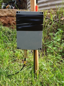
Here is the feed point, here I’ve temporarily strapped the matching unit and a 1:64 Transformer to the stake for testing until I come up with a more permanent setup. The capacitor in the matchbox can be adjusted so that X=0 on an Aerial Analyser or vector network Analyser.

20200510_113211

So how do you adjust something like this? how do you know it’s doing its thing?

Ok, lets go with what we know. We want the antenna to be resonant at 7.074 (in this case for FT8 mode on 40M) so we want a low SWR reading on this frequency and we also want the resistance as close to 50 Ohms as possible with a reactance close to 0 as well, to make our transceiver sing, and develop full power to the antenna.

I was actually quite gobsmacked at what I was seeing on the VNA. This is one of the first readings I took,  I set it to have a centre frequency of 7.075 Mhz with a 1 Mhz span. (this was straight after adjusting the capacitor in the matching box to peak the noise on RX with my FT817 Transceiver). This is what the VNA showed first up. The SWR is 1 to 1.16, the Resistance is 58 ohms with 24.nF of reactance. The frequency is shown as 7.005 Mhz. Moving the marker (the little triangles on the VNA screen) so the reactance is very close to 0, (resonance) showed a frequency of around 7.050 Mhz. So if we’re splitting hairs, the antenna is a fraction too long. The Mmana Gal model prediction seemed pretty spot on. I would only need to make minor adjustments to the lengths of the vertical radiators to shorten the antenna to raise the resonant frequency to 7.074 Mhz

20200502_192008

These numbers makes our Transmitter very happy to deliver full power to the antenna, no tuner (internal or external) needed…

20200511_220733

OK so the $64.000 question, does it work? Well yes, it certainly seems to!

I have the antenna orientated north/south, so it is radiating pretty much east west.

The antenna went up on the 2nd of May 2020 at around 5:00pm local time here in South Australia, here are the first few contacts on the antenna after calling CQ on 7.075 Mhz. 1st up is VK3FAC, who was receiving me at +10dB

Then followed by the USA,  Robert, K9U0 in Portland Oregon with a -13 report…nice, looks promising…

Then the friggen DOMINICAN REPUBLIC answers my CQ call!!! Migue HI3MPC with a -22 report…very nice!

Next? CUBA! Eduardo C07EPP answers at -17…Then I think I had to go have a lie down!! Here is a snippet from my log…LOG

The contact circled in green, with Slovenia is actually on 20M when I was testing the antenna with a 1:49 transformer to see if my radio would tune it on all bands from 80 to 10M with the rigs internal tuner, via the broadband 1:49 transformer…th 30, 17 and 12 Metre bands won’t match which isn’t surprising as they aren’t a multiple of 80, 40, 20 or 10…

So yes, it certainly seems to get out, and in the direction the modelling said it would.

I’ve worked 158 qso’s 19 DXCC entities so far in the 9 days as of 11/5/20 since the antenna has been up. I certainly do ok in the direction of the USA, Canada, the Carribean and Africa. An added bonus is the antenna is very quiet noise wise on RX, and the lack of horizontally polarised high angle qrm signals from Indonesia is noticeable. Also, I don’t get many JA stations returning my CQ calls as well, when before they were in plague proportions…this further reinforced the radiation pattern is favoring east/west.

So there you have it, I have described my journey with the Half Square antenna. I’m very impressed, I’m working stations I could only hope to before! I intend to try a portable version for 20M fairly soon, either near some salt water or a lake, as soon as these bloody social distancing rules are relaxed.

Happy Hamming, Andy, VK5LA

COVID19


The globe is certainly experiencing unprecedented difficulties and hardship in modern times. There is little doubt there will be much anguish and uncertainty for a long time to come.

The Riverland Radio Club is very mindful of the strain this is and will place on our radio community. Like many radio clubs many of our members fall into the vulnerable category for a variety of reasons.

To this end our Club has opted to suspend ALL Club face to face contact, including Business Meetings and Tech Nights, to play our small part in flattening the curve. We recognise this action increases the sense of isolation which we feel is in conflict with mental well-being.

So to support our members though this uncertain time we have committed to undertake the following:

  • Business Meetings for Club members to convened over the VK5RLD repeater;
  • Tech Nights replaced with a 80m (3650kHz) Net, all welcome;
  • Members, and all comers, are encouraged to join the WIA News Re-broadcast call backs; and
  • Check into the RRC BRL Nets
    • Sat & Wed, 7115kHz, 0830hrs local
    • Tue, 3610kHz, 2000hrs local).

To all the HAM community, stay safe, stay well, stay vigilant.

Danny VK5DW

2020 BRL Gathering Registrations

POSTPONED   POSTPONED   POSTPONED

RRC regrets to advise the postponement of the RRC BRL Gathering

Saturday, 18th of April, 2020

Ok Folks, come one come all, it’s on again, the BRL Gathering for 2020 is on Saturday, the 6th of April, at the same sensational location, famous for its picturesque setting, Fantastic Hospitality, Great Food and Cold Beer.

DUE TO COVID 19 RISK THE GATHERING HAS BEEN POSTPONED TILL FURTHER NOTICE

Print

Lunch –  Lunch at the Hotel is a must! Check out the menu and get your taste buds excited for April. The Hotel’s food is renowned for its quality and value!

*Dogs are welcome at the Overland corner Hotel*


A 3/8 wave vertical for 20m


Building this antenna came about after I wanted to put something up at home specifically targeting 20M FT8 on 14.074 Mhz.

20191020_172253

The 3/8 wave vertical for 20m in my front yard…

I’m fairly time poor so I needed something quick, simple and cheap to get going with asap. Whilst doing a bit of research I came across the winners of the 2018 QST Antenna Design Competition, and interestingly, third place was a 3/8 wave vertical for 20M by Joe Reiart, W1JR. As I’m not an ARRL member, I asked if anyone in my HAM community  would be kind enough to let me have a copy of the article. Several people kindly sent it to me.

Surprisingly, there is virtually nothing on the internet about a practical example about this antenna. I did find an old reference to the antenna, but no solid build details.

In a nutshell, according to the article, the 3/8 wave vertical has the advantage of requiring less radials than your standard 1/4 wave, but is about 50% taller for the same band. A 1/4 wave vertical requires at least 16 1/4 wave radials for good performance due to the low feed point impedance of around 35 ohms, whilst the 3/8 wave requires just 4, having a feed impedance of around 200 ohms. It also sports a lower take off angle of radiation of 23°,  vs 26° for a 1/4 wave (better for DX), and as the radiating current maximum point is 1/8 wave up the vertical instead of at ground level, it is ideal for ground mounting in situations of nearby clutter. It is easy to match to 50 ohms Coax via a simple 4:1 Unun and a series capacitor.

The materials

I decided to go with a squid pole for the vertical radiator, as they are cheap and easy to keep in the air, so I purchased a 6M pole to which I added 2 base sections from older broken squid poles to bring me up to 7.5m in length. This size slides neatly over 38mm PVC pipe, which is the diameter of my portable stand mount that I use for field work. I also had to purchase the 2, FT240-61 Ferrite cores for the Unun and choke, ( I got mine from Minikits in Adelaide) and a box for the Unun (Jaycar) at the feed point. So for less than $100 I was ready to go.

The Unun

20191015_142101

The 4:1 Unun…

This turned out to be very straight forward, and is explained in the article. There is quite a bit online about 4:1 Ununs, I’m sure you’ll have no drama constructing your own. I used Jaycar red and white power cable cat. No. WH3057, I stripped off the black outer PVC sheath and lightly twisted the wires in a drill, then wound on the FT240-61 ferrite core to get the result shown in the above pic…

The In-line choke

The article is fairly vague on this describing it as 10- 12 turns of RG-303 wound “W1JR style” A quick Google returned lots of hits for this, and you can see my resultant choke in the pic…I used RG-316, as it was what I had lying around.

20191021_170534.jpg

The W1JR choke…

Mounting it

By now, I had gathered all the materials I needed so it was time to put the antenna together and see if it did what it was supposed to do.

I initially mounted the antenna on one of my ALDI bike stands as that’s what I normally use for testing and portable operating but my initial tests showed there was a LOT of interaction with the stands metal base/legs and support and the antenna. Readings on the antenna analyser were nothing like I was expecting and confirmed when I moved the Unun away from the base, the readings began to move towards something more like I was expecting.

So I then decided to shift the whole shebang to my PVC vertical antenna mount in my front yard…

This is simply a length of PVC pipe driven into the ground and about 600mm protruding out to mount antennas on, with a short extension that the squid pole just slips over…simple! The pictures below show how…


I set the whole thing up, with the vertical wire length calculated to 8.010 metres in length and the matching unit lying on the ground with the 4 radials connected. This showed the 50 ohm point to be around 13.8Mhz, so I shortened the antenna to raise the 50 ohm point to 14.075 MHz. I had a variable capacitor in between the unun and vertical, so I adjusted this capacitor to bring the X=12 reading on the analyser to zero. This measured at 7pf, close to the 10pf mentioned in the article…

Gotta be happy with that!


The squid pole ended up being about 7.5 m in length, so the vertical wire and match box at about 7.8m hung just nicely just above the ground on the mount. You can see the match box with its coax capacitor, how the choke ( to keep RF of the coax outer) connects to the match box and where the 4 radials attach…


I only had a brief opportunity to have a listen with the FT817 on the antenna, and the receive was very lively, especially on the frequency of interest. SWR was flat, with the radio developing full power on TX.

I’ll update this article when I’ve had a chance to evaluate the antenna on the air…

Andy, VK5LA


Reference: The 3/8-Wavelength Vertical – A Hidden Gem. Joe Reisert, W1JR P44 QST April 2019.