A Tuned Counterpoise Vertical for 30 and 20M –

Hi all,

I’m presenting here a compact, completely self contained vertical antenna that I have conceived,  designed and built recently. This antenna is primarily for portable operation on the 30 and 20 metre bands (although it could be easily adapted for other bands). Being a portable antenna, it had to tick a few boxes, as I intend using it on some planned VKFF park activations that will be taking me near salt water…

  1. Be light weight – Fiberglass, aluminium, nylon and stainless construction
  2. Be compact – The entire antenna packs down into a package no longer than 1.5 metres
  3. Be quick to erect – The antenna mounts on one of my ALDI Bike repair stand tripods that I use for portable operations and deploys in minutes.
  4. Plug and play – Low maintenance, simple 50 Ohm Coax feed, no traps, easy to adjust
  5. Be a good performer – Initial tests indicate it is an effective low angle radiator.
  6. Have a very low environmental impact – Some park environments are fragile, so a stand alone antenna that uses no vegetation/natural features as supports protects that environment
Tuned5LA

Fig. 1

The inspiration for this antenna came after I came across this video from Peter, VK3YE back in 2015 on his most excellent YouTube channel. The construction details on his antenna were unfortunately rather brief, but used telescopic rabbit ear TV sections as his counterpoise, and a section of coil stock which he taps to bring the counterpoise to resonance against a quarter wave radiator. It’s wonderfully simple. Peter drew a diagram in the sand, but i’ll put one here…

Figure 1 shows the antenna. It consists of a 1/4 wave vertical radiator, with an Elevated, short counterpoise, that is tuned to resonance (think of it as the other half of a dipole with the 1/4 wave radiator) by adjusting the inductance of the ground tuning coil.

I just like to mention that I haven’t invented anything, but other than Peter’s video, I haven’t been able to find any concrete reference or practical examples to this kind of antenna on the internet. Peter mentions a page in Les Moxon’s “HF Antennas for all Locations” describing a short tuned counterpoise, but the second hand copy I hunted down (ISBN 0 900612 57 6) doesn’t have the same information. The diagram shown on page 186 in Peter’s version of the book in the video appears on page 157 in my copy. There is only a vague mention of the same concepts, nor is there any solid measurements or construction tips.

30m-tuned_counterpoise_quarterwave

Fig.2

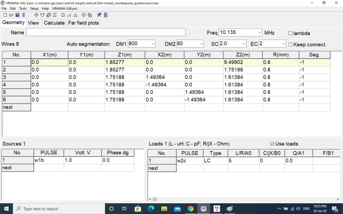
I have become reasonably adept at modelling and tweaking simple antennas in MMANA-GAL  Antenna modelling software. This is an excellent, free program that lets you visualise and design an antenna, and play with it to tweak its performance. I’m no expert, but after a short learning curve I’m able to do pretty much what I need to do reasonably quickly. So I drew the antenna thus… In figure 2, you can see the feed point – the red dot, the 1/4 wave radiator above it, and the  4 short counterpoise wires below. The ground tuning inductor isn’t shown, but is actually described in software. The wire I used as a radiator is just heavy duty grey plastic insulated wire. It has a velocity factor of about .93 so my 10.135 Mhz 1/4 wave is 6.875 metres long. The counterpoise “wires” –  actually 6mm aluminium tubing, are all 1.5 metres long. The lowest point of the antenna is at 1.00 metres from the ground, as this is the height bottom of the antenna stops when slid on to my portable mast mount. 

Ok, so what about the short counterpoise? How do we tune the antenna to resonance? We know the radiating element is at a 1/4 wave for our band of interest – in this case 6.875 metres long. Let’s add a short wire between the feed point and our 4 counterpoise wires to add a coil to…

W2View

The red wire shown in the model is only 100mm long, but is used to define where we will put our coil to bring the 4 short radials to resonance. This is defined as Wire 2.

Now we have the antenna defined in the program, We need to tell it that we are feeding the Antenna at the bottom of Wire 1. This is in the table Sources 1 w1b. The inductor is defined in the Loads 1 table The coil is defined here as w2c – i.e the coil is in the centre of Wire 2 and has a value of 5 uH. ( This was initially 20uH…it was twaked to 5uH to get the SWR down)

Loads

Ok now we can run the software to see what the antenna model will look like…

Calculate

So here we have the result. Here we can see that the antenna has a feedpoint impedance of close to 40 ohms resistive, 8 ohms reactive with a SWR of 1.33. (This result is after I tweaked the value of the inductor from about 20 uH to 5 uH) The base of the antenna (tuned ground radials) is at 1.00 above real ground.

Lets look at how the antenna is radiating RF according to the software, here are some plots…

Plots

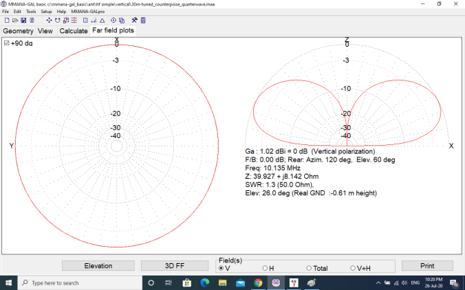
This shows the gain of the antenna is about 1.00 dBi, and the maximum radiation is at around 26 degrees towards the horizon.

Now we have a model that says what I have envisaged, should, in theory, work!

Let’s build it!

Pictures tell 1000 words so here is some shots of the various parts…

The Main radiator is a 9 Metre Squid pole, this slips over a 42mm PVC extension that slides into the top of the ALDI bike repair stand I’m using as a tripod. The top and bottom coil supports are cut and drilled from Nylon cutting board. The 4 radials below the coil attach to the triangular aluminium plate on the bottom coil support. The bottom of the coil is connected here, and the top of the coil is connected right at the earth connection of the SO239 socket on the top coil support. The Coil is soft aluminium craft wire, readily available from ebay. It’s easily formed into a coil and is slightly “springy”. There is a nylon clamp on the top coil support that allows the top support to move up or down, thus stretching or compressing the coil, to tune the antenna to resonance. The clamp secures it when the adjustment is completed. The 1/4 wave wire attaches to the centre conductor of the SO239 socket, and is loosely wound up the squid pole mast and secured. There is a common mode choke just below the feed point, it’s 17 turns of the coax through a single FT240-52 toroid. (shown here as RG174, since changed to RG58)

So what does our trusty nanoVNA tell us? After adjusting the length of the coil this is what the 30M band looks like…The antenna seems to be doing exactly what it should. Feed point resistance is 47.7 ohms, there is 1.36 nanofarads of capacitive reactance and the SWR is 1:1.26 .have to be happy with that…

20200725_124707.jpg

I also experimented with a 20 metre band radiator, and added a shorting clip to shunt out some inductance to bring it resonance on 14.075…Here our SWR is 1:1.19…so its working here as well…

So how does it work on the air? It’s early days, and I had it set up very close to my house and fence, but the path to my east was clear and it certainly seems to get out. Some good DX to El Salvador and Guatemala on 30 metres FT8 was worked in the first few hours on the air…I easily worked the USA as well on both 20 and 30 metres. (all East of me)

I’ll set this Vertical up in the clear on my block away from buildings in the next couple of days and see how well (or not) it works compared to my reference antenna. I’m hoping the low take off angle will allow me to work the more distant stations my reference antenna seems to struggle with.  I’ll update here when I’ve had more time to judge it’s performance.

I hope the information presented here is of interest to some. I really enjoy modeling and building antennas, but I’m pretty green! I’ll readily admit to not understanding many aspects of RF and I have no idea how efficient this antenna is, my ground losses, etc etc. I guess it’s all about learning and experimenting. I welcome any comments or criticism, please feel free to contact me if you would like any more details on what I’ve described here…

73

Andy, VK5LA

andyvk5la@gmail.com

***UPDATE***

Very happy with the antenna, I worked 100 countries in 7 weeks, pretty good going at solar minimum!

Some ideas for RX noise reduction and a Mains Filter for your Radio Shack…

Got Noise? -Then this might get you back on HF if you’ve switched off because the “S” meter is S9 or S9+ when you turn on your rig, especially on the lower 160-80-40-30 Meter Bands…

If you live in suburbia, or even semi-suburbia, you might have, or are currently dealing with, high levels of noise in your Receiver when operating your radio. This is usually the worst when you’re trying to work that rare DX, a weak digital signal or even just your club HF net or Society news broadcast. Noise can be wearing. I have heard of many an Amateur that has switched off due to excessive noise and placed their hobby in the “too hard basket”. I even personally know of two radio friends who sold up and “moved to the country” in search of that holy grail of noise levels…S0.

I don’t claim I’m going to fix your noise issue but hopefully I can offer some guidance and experience in dealing with radio noise in the HF spectrum in your environment.

Firstly, If you can, set up your radio to run of of a battery and plug in your main antenna. Cut the power to your WHOLE HOUSE, (yes go out to your meter box and throw the main switch!), so that nothing is energised on your property. (Also cut your Solar if you have it and are able) Now see what your noise level changes to. Chances are, the noise level will drop, sometimes significantly. This is actually a good thing, because it means that it is highly likely that the noise source is at your place, and you can do something about it. More later.

If your noise doesn’t change significantly, then the likely scenario is that that your antenna is picking up a noise source from a neighbor, or a utility such as a nearby power line or other service.

***My first piece of advice is to make sure that your antenna feed line has a common mode choke.***

This will need to go at the feed point if it is a coax fed dipole or variant, or right at at the radio if it your antenna is an End Fed Half Wave or similar. If you are unsure what a common mode choke is, then grab a coffee, and  have a look at this from Steve, G3TXQ (SK).

Now have a read of this from Jeff, K6JCA. Both links are extensive and extremely informative.

If you’re still not convinced that you need some kind of common mode choke on the feedline of your antenna, please have a look at this video.  You can clearly see the effect on both Receive and Transmit.

Now back to our main objective, let’s look at another known source of noise, the very common Switch Mode Power Supply. These. things. SUCK!!! They are known generators of RF noise and interference. Generally, their cost is inversely proportional to the amount of RF they generate! The cheaper units leave off a few cents worth of EMI suppressing components to make them as nasty as can be. Most modern households these days have many gadgets and low cost Asian electronics, and they often come with one of these Switchmode power supplies. Phone and Tablet chargers, computer and laptop power supplies, garden and Christmas lighting, toys, decorations and fixtures containing electronics, LED light fittings and bulbs…Just about everything these days has an SMPS. Some are clean, but many can be excellent generators of broadband RF hash. Indeed, some can completely wipe out radio reception up into the UHF range, (like the charger our boys portable DVD player!!!)  The best way to find them is by a process of elimination, simply by going around the house and turning stuff off at the wall. This will soon expose the culprit , but don’t forget you need to cut the power to the particular device completely, not with just switching of with a remote or the front panel power switch, as this usually just turns off the displays, (think home electronics, Audio Visual gear etc. etc.) and the unit is still effectively powered up, and still drawing current from the power supply.

I had a particular problem with the power supply for my shack laptop, which is a Dell Lattitude E6410. Even though Dell is a reputable brand, used by business and governments around the Globe, the power supply generated a bad hash causing up to an S7-8 noise level, from 80-20 metres.

wp-1591267938406.jpg

Simply wrapping the power connector lead through a FT240-43 Toroid core as pictured above, went a long way to eliminate this noise. The difference was remarkable. A point to note was that the power supply itself had just about every compliance tick and UL listing .

wp-1591269468755.jpg


They mean nothing!


***My second piece of advice – hunt down, find and eliminate any cheap Switchmode Power supplies***

Replace them if you can, or alternatively get some ferrite rings and wrap the output leads through the cores as many times as you can.

Other sources of noise can be from the cables coming from your shack computer to peripherals such as printers, keyboards and mice, displays and USB leads and hubs etc.etc. Give these the toroid treatment as well, everything helps. (As an example, here is the USB lead from my laptop to the USB mixing desk I use to route microphone and other audio to my main HF radio directly into the balanced modulator), and to the little Raspberri Pi I use for digi modes. These all help in the scheme of things to drop your RX noise closer to S0. If possible switch to a bluetooth mouse and keyboard if you’re running a PC . This eliminates 2 leads from radiating computer hash in your shack.


Sometimes, noise can come from the 230V mains supply to your shack from many different sources. Perhaps from an appliance located at your or a neighbours house, such as a dishwasher, washing machine, deep freeze, hot water heater, solar hot water booster, microwave etc.etc if they are on the same supply phase. The noise this equipment can generate could radiate to your station via your power supply.

This is where this mains filter comes into play. Just like a common mode choke on our feed line (you have installed one, haven’t you?) the best way to eliminate or greatly reduce supply noise is to have a mains filter that incorporates a 2 stage EMI Filter with some hefty, multi frequency common mode choking of the 230V supply, before it powers the equipment of your shack.

After doing a bit of reading and on the advice of others, I was directed to this most excellent presentation describing a holistic approach to finding and eliminating such noise and the construction of such a filter by Ian White, GM3SEK, and the update here.

Here I’m describing my version of the filter that I built. Anyone should be able to reproduce this filter, using parts that were easily obtainable here in Australia. My parts came from Jaycar, RS components, Bunnings and Cheap as Chips.

***Disclaimer – this project describes working with Mains Voltage!!! ***

***If you are not experienced with working with the 230V mains wiring, find someone with expertise to assist and check your work!***

Parts List:

  • 1 x Sealed Polycarbonate Enclosure 171 x 121 x 80 Jaycar Cat No. HB6224
  • 1 x EMI Filter  – I had mine laying around, see Note 1 – RS Components
  • 1 x Fair -Rite Large Ferrite core (clamp type) RS Components Stock No. 466-9164
  • 4 Small Ferrite cores, Jaycar L15 Cat No. LO1238
  • 1 x 10 amp 12 way Terminal strip (chocolate block) Jaycar Cat No. HM3196
  • 1 x length 10 amp extension lead – Cheap as Chips
  • 1 x 6 outlet power board overload protected – Cheap as Chips
  • 2 x 16mm Cable Glands – Bunnings

Note 1: Delta Electronics 10 DRC5W 250Volt 10A 2 Stage EMI Filter or equivalent. I used one I had kept from an old Photocopier, hence the surface rust ! Just about any EMI filter with a 10 amp rating should do, RS Components lists many single and double stage filters that would be suitable.

A picture tells a thousand words, so here is how my filter came together…

This slideshow requires JavaScript.

wp-1591764985009.jpg

The completed unit with the lid off…


The end result is shown here. The filter simply installs between your wall socket and your equipment. The Cable glands grip the cable to prevent it from being pulled out. Cord grip grommets like Jaycar CAT No. HP0718 would probably be better, but I had the glands, so I used them.

So how does the filter perform? I have been using the filter for a little over a month. My location is quite good for HF and I am blessed with a quite low noise level on most bands, it was reasonably high on both 80 and 30M. I am unsure of the sources (it’s not my place) and my nearest neighbor is 250 metres away. The filter has dropped my 80M noise from S8-9 back to S3-4. this is a significant improvement on that band and I have been able to make contacts I probably would have struggled with previously. My noise on 30M did seem to come and go, noticeably with the operation of our dishwasher and washing machine. There can also be a bit of a noise hash on this band that was sometimes up to S7. I’m pleased to report that the hash has been significantly reduced and my 30M noise level sits at around S1, and I can no longer tell when the dishwasher is on! I like to take a holistic approach to noise and this filter has made a difference.

This is a simple project that might significantly reduce your noise level in the shack – build one and let me know if it works for you!

73 – Andy, VK5LA