Hi all,
Bob VK5FO here, I just wanted to share a little about something that I do in Radio …
I enter the OCDX Contest each year. A bit more info here: http://www.oceaniadxcontest.com/index.html
This is the contest where all beams are pointed to VK and… you work em!
Now, I do it the hard way, I enter the Voice QRP Single Operator Category and in 2016 I was 1st in Australia, 3rd in the World. In 2017 I was 1st in Australia and 2nd in the World. Here’s hoping that the first weekend of October 2018 is kind to me and I can jump up to Number 1.
Now, the last couple of years I have been pretty casual about my set up and not really hitting it too hard, but this year, I have been doing a whole lot of stuff with Antennas. And let’s face it, QRP means that I need to best possible Antennas. I concentrate on 40M, but contacts on 80, 160, 20, (and 15) all help give multipliers, with the points favoring the lower bands.
The last couple of years I have just used very basic antennas:
- a ~55M end fed wire for 160/80/40;
- a 40M inverted V (also used on 15M);
- a 20M dipole; and
- the Multi-band vertical which covers from 160 thru 10.
So, this year, I have already started to go “all out” in the antenna department and this weekend just gone, I put up a monster 40M antenna that has already proven to be awesome, onto that a bit more in a minute.
What I have done is taken a bit of time and learnt a tiny bit about modelling Antennas with 4nec2 software, available from: http://www.qsl.net/4nec2/. And yep, it’s free software.
So I learnt just enough about how to use 4nec2 and do some modelling and started off with simple inverted V which I used as a basic “reference”, basically confirming that what was modeled is what was happening… which is pretty close.
From there, I then put in the details of the end-fed wire I used last year and modeled it across the 3 bands I used it on. And this is where I learnt what a crap antenna it really is and started looking at what I could do within the confines of what I had to work with, space wise and of course elevation for the Antenna itself.
That end-fed wire was so rubbish on 40M it is a wonder I made as many contacts as I did; with massive lobes and nulls and horrid very high angle radiation.
So, a few weeks ago, I did a log analysis from last years contest and looked at where in the world I needed to send RF and started to work on a 40M Model. I came up with something that I am very happy with… 40M Bob OCDX Special
 Let me explain a little about this pattern:
The red line is the horizontal pattern and there is a very nice lobe sitting towards the 90 on the plot (which I have pointed North); within the 3db points of the lobe it nicely covers EU for the morning greyline and the US for the evening greyline, as well as all of Asia due north as well.
By not transmitting out the back and pushing it forwards, where it is needed, already compared to my model of last year’s antenna there is around 12 to 14db more signal where I need it compared to last year. Or effectively taking my 5W signal and running around 120W – equivalent!
That is not the whole story… look at that wonderful blue elevation on that plot, it peaks at around 30 degrees and again a nice null off the back where It is not needed, but still “just enough” high angle signal so that the NVIS contacts during the day can be made.
We put this antenna up on the weekend and used it on Saturday night, when we were swapping it in and out against our reference antenna it was chalk and cheese – Massive improvement! US voice went from 3×7 reports to 5×9 +20+ and we could also hear all the other stations on the net as well!
So we will be giving this a bit of a work-out over the coming weekends!
Now, the next challenge is 80M and as I cannot get a dipole up to 40M high (nor can many people) I set about doing some further modelling and I will be putting up an 80M antenna on the weekend and seeing if the model actually does what I see on paper.
 Just like the 40M model, I worked with what I had and looked for how I could do something with what space I have.
See the 80M REF Inverted V plot – this is an 80M dipole at 8M high – something along the lines of what most of us can do – and as you see – it is ONLY an NVIS antenna – everything is up baby – not much below 45 degrees – and of course – the lower the better for DX.
Now look at the 80M low and low plot – This is what I 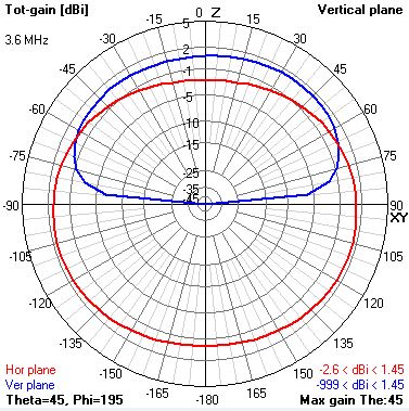 am going to install this weekend and try.
First off – the Red line – horizontal pattern – it has to nulls off to the sides of around 4db, which I can position such that my signal goes where it is needed in the other direction.
The big 1 here is of course the Vertical pattern – you will see that I have managed to create a pattern that is pulled right down low – right down to about 30 degrees – so a LOT more signal is going out and not straight up!
Now, if this works as modeled, and if we look at 30 degrees elevation vs the reference it is around 4 or 5db better – which should be a big improvement.
The best part is this antenna is NOT BIG! and not tall, but does need a fair bit of open and clear space (being 80M and all!) It is not a lot bigger than the inverted V – and yes it is only 8M high as well!
On 80M, the reference dipole is very similar to my end-fed wire used last year – with it being mostly a sky warmer.
So far, my modeling for 160M means I am going to be stuck with pretty much whatever length of wire I can put up that doesn’t interfere with the other antenna’s – this is a harder one to improve, but hey, if I can managed 10 or more contacts on 160, then that is about what I expect.
20M well, I have a suitable antenna – and 2 elements that I use when portable will be put into play – and it is a known performer.
If you have got this far thru my ramblings – congrats!
What I am hoping is that I can get along to the Nov meeting and show you guys some 4nec2 modelling and how you might be able to do some basic things such as putting in your antenna, then we can play around and see if we could improve it – no promises, but I hope I can make it.
And…. If you happen to hear me on the contest weekend – I would love extra contacts on as many bands as you can muster for me.
Also, given that I do this contest from the Riverland (where I have the space to put up a very large antenna on 40M) There is an open invitation to pop along and see what it takes to set up and run a contest station like this – We just need to know if you plan on coming and when over the weekend.
And as a final footnote – whilst my callsign has a certain schoolboy smut amusing factor to it, it is an absolute nightmare in a contest!
So I have applied for and been granted a new callsign of VK5HC which I will be using for contests only.
Cheers,
Bob,
VK5FO

Best of luck Bob, I hope to work you. Thanks for an interesting story Thank you for the offer to present the modeling software at a future meeting. I wish you all the best VK5HS
LikeLiked by 1 person
Pingback: Update on VK5FO’s Contesting | Riverland Radio Club